As DRAM cell scaling reaches its limit, SK hynix is conducting various studies to continue the advancement of DRAM technology. The company and DRAM manufacturers face several challenges as they look to push the boundaries of the technology. One of the most significant issues faced by the industry is the required capacitance* must be maintained even if the area of the DRAM cell capacitor is reduced. In order to meet the requirements for future DRAM cell capacitors, it is therefore imperative to develop ultra-thin dielectric* (DE) materials with a higher dielectric constant* (K) and low-leakage currents.
*Capacitance: The ability of a component or circuit to collect and store energy in the form of an electrical charge.
*Dielectric (DE): Insulators that become polarized to support an electrostatic field when they are exposed to an electric field.
*Dielectric constant: A value representing the electrical dielectric properties of the dielectric. The higher the dielectric constant, the more charge the dielectric can accumulate.
To further the development of such materials, SK hynix’s Revolutionary Technology Center (RTC) conducted a study which fused ultra-thin ferroelectric* (FE) and anti-ferroelectric* (AFE) materials, respectively, with ultra-thin dielectric materials as shown in Figure 1. This article will summarize the process and results of the study, which were first announced at the IEEE Electron Devices Technology and Manufacturing (EDTM) Conference 2023.
*Ferroelectric (FE): A material which exhibits spontaneous electric polarization without an external electrical field that can be reversed in direction by the application of an appropriate electric field.
*Anti-ferroelectric (AFE): A material which exhibits ferroelectric polarization properties in external electric fields but does not have spontaneous polarization in the absence of external electric fields.
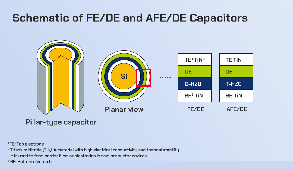
▲ Figure 1. [Left] Schematic diagram and planar view of FE/DE and AFE/DE pillar-type DRAM capacitors with the same structure. [Right] Thin films of O-phase rich HZO FE double layers and T-phase rich HZO AFE double layers are applied to determine which is most effective.
To determine whether FE or AFE materials are more suitable for use as a DRAM cell capacitor, hafnium zirconium oxide* (HZO)-based FE (O-phase* HZO) and AFE materials (T-phase* HZO), which are highly compatible with the CMOS process, were used to manufacture ultra-thin FE/DE and AFE/DE double layers.
*Hafnium-zirconium oxide (HZO): Oxide (HfZrO2) consisting of hafnium (Hf) and zirconium (Zr).
*Orthorhombic phase (O-phase): A crystal structure with three different axes at right angles. O-phase HZO shows ferroelectric properties.
*Tetragonal phase (T-phase): A crystal structure in which three axes are at right angles and two of them are the same. T-phase HZO shows electrical properties similar to anti-ferroelectricity.
For the study, the FE and AFE properties of the fabricated double layers were controlled. An analysis was conducted of the correlation between equivalent oxide thickness* (EOT), a key characteristic of DRAM capacitors, and residual charge* (Qrem), a core property of ferroelectrics.
*Equivalent oxide thickness (EOT): The thickness of a transistor’s silicon oxide film that would be required to provide the same electrical performance as the high-κ material being used.
*Residual charge (Qrem): Polarization remaining in ferroelectric or anti-ferroelectric thin films.
As shown in Figure 2, the capacitor composed of FE/DE showed a trade-off relationship in which the EOT greatly improved, but the Qrem increased rapidly. This was due to the sharp increase in the FE characteristics of the FE layer and the spontaneous polarization properties, causing a rise in the residual polarization. In contrast, the AFE/DE capacitor demonstrated a small improvement in EOT and a minimal increase in Qrem because the spontaneous polarization characteristics of the AFE were very low compared to the FE.
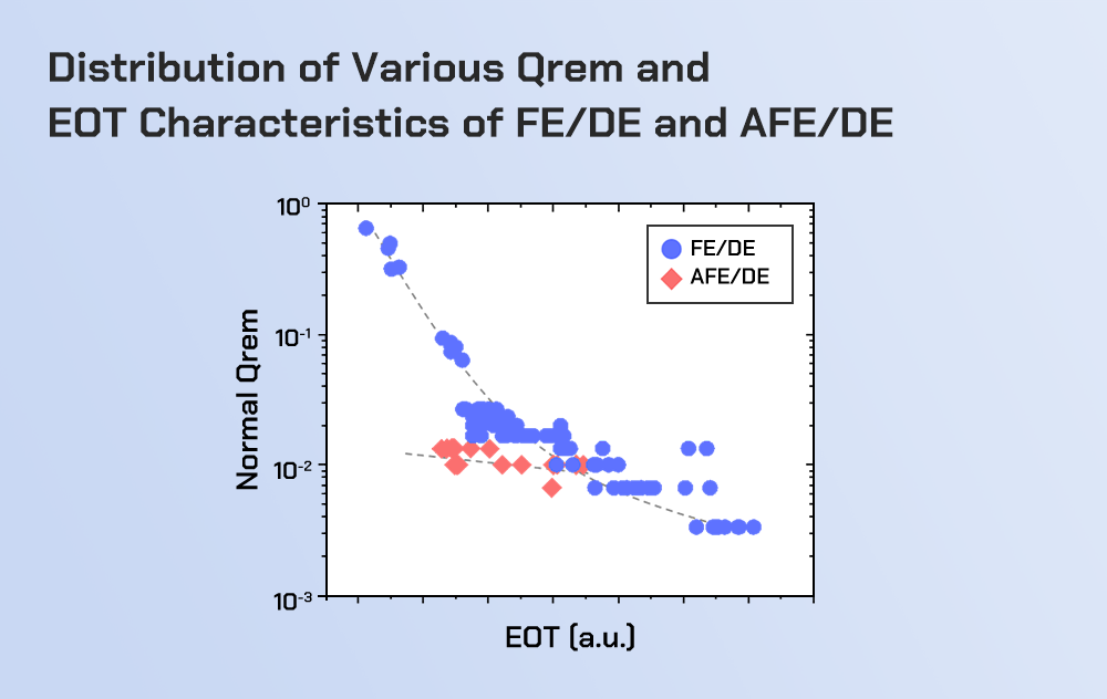
▲ Figure 2. A scatter graph showing the distribution of various Qrem and EOT characteristics of FE/DE and AFE/DE materials
In order to analyze the difference in the operation of DRAM cells according to residual polarization characteristics, the breakdown voltage (BV)*, a major trade-off characteristic of capacity, and capacitance values of AFE/DE and FE/DE were evaluated (Figure 3). The two capacitors showed similar BV and capacitance values, but there was a significant difference recorded in DRAM cell operation (Figure 3a).
*Breakdown voltage (BV): Minimum voltage at which part of the insulator is electrically destroyed and becomes conductive.
DRAM cells using the AFE/DE capacitor showed significantly less tWR* and FBC* than DRAM cells with the FE/DE capacitor (Figure 3b). This is because when the data write operation time of the DRAM cell is checked through the tWR test, a relatively large amount of Qrem characteristics caused by the ferroelectricity of FE/DE act in the opposite polarity during the write operation. This hinders the subsequent DRAM operation, and the write operation does not function correctly. Therefore, when using FE and AFE as DRAM capacitors, it is important to consider not only the capacitance and BV characteristics (leakage current), but also the Qrem properties.
*Write recovery time (tWR): The appropriate amount of time required for data to be written to a DRAM cell; insufficient tWR will cause data errors during data read and write operations.
*Fail bit counts (FBC): Number of fail bits generated by one wafer during DRAM operation evaluation.

▲ Figure 3. Results of selecting and evaluating AFE/DE and FE/DE with similar BV values and capacitance. (a) Scatterplot of BV and capacitance properties of FE/DE and AFE/DE (b) 12-inch wafer map for tWR fail bits in DRAM cells (c) correlation graph of FBC and Qrem properties.
In summary, this study investigated the electrical properties of FE/DE and AFE/DE materials and verified actual operation in DRAM cells. FE/DE materials demonstrated excellent potential for reducing EOT, but it was confirmed that the probability of fail bit generation during the tWR test increased rapidly due to its relatively high residual charge characteristics. On the other hand, AFE/DE is limited in reducing EOT, but the probability of fail bit generation during the tWR test is reduced due to the relatively low residual charge characteristics.
It was therefore concluded that AFE/DE is more suitable for use as a DRAM cell capacitor than FE/DE because residual charges must be strictly controlled for stable DRAM operation. To realize further miniaturization of DRAM technology, various new methods will need to be developed and verified to secure materials with strong FE characteristics.
For more information regarding RTC’s research, please visit the center’s research website (https://research.skhynix.com). The RTC operates the site to share insights on its ongoing research of future technologies and to actively communicate with various global research organizations.