To each sheet of wafers that have completed the front-end process, 500 to 1,200 chips, which can be also called dies, are attached. To use each chip for the required field, it is necessary to perform a dicing process for dividing them into individual chips and connect them with the outside, using wires to allow electrons to flow. At this time, the method of connecting the wires, which are the paths of electrical signals, is called wire bonding. In fact, using wires to secure electrical paths is a classic method, which is now used less and less. Recently, flip chip bonding, also known as bump bonding, which is a bonding method using small bumps called solder balls, and another method known as through-silicon via (TSV), a more advanced method, are becoming mainstream. In this article, however, we will take a look at wire bonding to learn more about the basic concept of bonding.
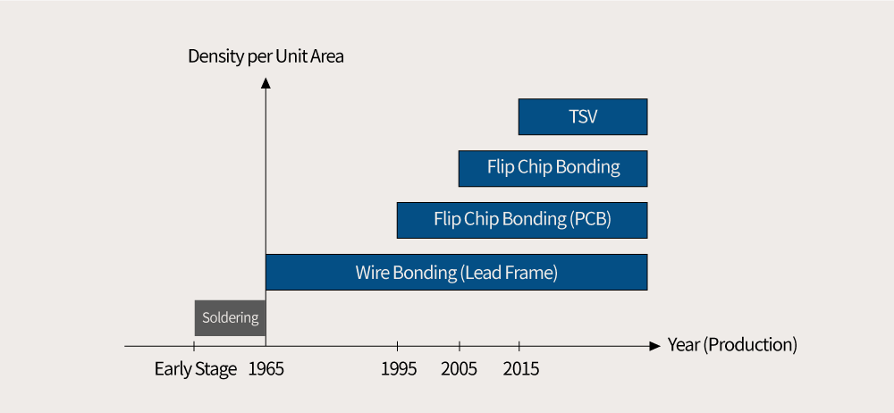
▲ Figure 1. Development of bonding methods: Wire Bonding → Flip Chip Bonding → Through-Silicon Via (TSV)
For a semiconductor chip to operate normally in various fields, a bias voltage and input should be supplied from the outside. To do this, the bonding pads of chips should be connected to wires. The method of connecting wires started with soldering in the early days and has developed in various ways from 1965 to recent times including wire bonding, flip chip bonding, and TSV. Wire bonding uses fine wires for connection while flip chip bonding uses bumpers instead of wires to increase the flexibility of the wire connection. TSV, an approach with a completely new concept, allows the upper and lower chips to be interconnected with a printed circuit board (PCB) through hundreds of holes.
2. Comparison of Bonding Methods: Wire Bonding and Flip Chip Bonding
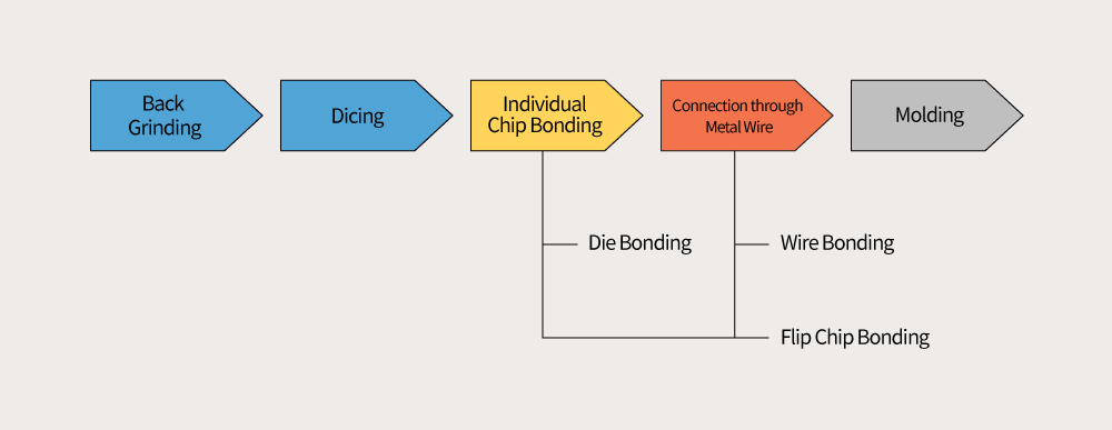
▲ Figure 2. Process of wire bonding and flip chip bonding
Die bonding performed after the dicing process is a process to fix a chip to a substrate, and wire bonding after die bonding is performed to secure electrical signals. Another connection method similar to wire bonding is flip chip bonding. ▶ Refer to <Die Bonding, Process for Placing a Chip on a Package Substrate> Both of these methods connect the bonding pads in chips and the pads on PCBs using metallic objects with a small diameter (in the case of a lead frame, it is used only in wire bonding). Wires in wire bonding have several disadvantages. As the length is longer and the diameter is smaller compared to bumps, it takes a long time to transmit an electrical signal and the signal can be easily distorted due to the high impedance of the wires. Also, the solder neck is easily disconnected or the bonding strength is weak, resulting in poor tensile strength. On the contrary, flip chip bonding has many advantages in connection reliability and electrical signal transmission even though it is more complicated to handle because the solder balls used as connectors are very small.
3. What is Wire Bonding?
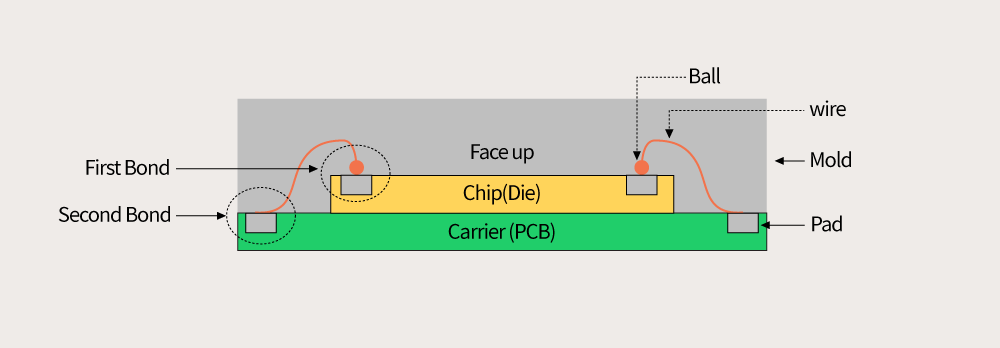
▲ Figure 3. Structure of wire bonding (When the carrier is a printed circuit board (PCB))
Wire bonding is a method of bonding thin metal wires to a pad, as a technology that connects the internal chip and the outside. In terms of structure, wires act as a bridge between the bonding pad of the chip (first bond) and the pad of the carrier (second bond). While lead frames were used as carrier substrates in the early days, PCBs are more frequently used now with the advancement of technology. Wire bonding, which connects two pads separated from each other, can vary greatly in terms of wire material, bonding conditions, and bonding location – not only between a chip and a substrate, but also between two chips or between two substrates).
4. Wire Bonding Methods: Thermo-Compression / Ultrasonic / Thermosonic
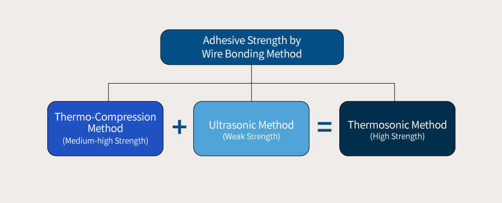
▲ Figure 4. Wire bonding methods
There are three main ways to connect wires to pads, which include the following: The thermo-compression method where the bonding pad and capillary, a capillary-like tool for wire transfer, are heated and compressed for connection; a method of bonding, by applying ultrasonic waves to the capillary without using heat; and a complex method that uses both heat and ultrasonic waves at the same time. In the first method, which is the thermo-compression bonding method, the temperature of the bonding pad of the chip is raised to about 200℃ in advance. Then, the temperature of the tip of the capillary is also raised to make the wire into a ball, thereby applying pressure to the bonding pad through the capillary to attach the wire to the bonding pad.
Secondly, the ultrasonic method is a method of attaching the wire to the pad by applying ultrasonic waves to the wedge, which is a tool transferring wires like a capillary, but without forming a ball, while pinning down the wires against the pad surface. This method has the advantage of low cost in terms of process and material; however, since it uses ultrasonic waves which are easy to handle, instead of heat and pressure, the bonded tensile strength, the strength to withstand when the wire is pulled after wiring, is comparatively weak.
The most commonly used method in the semiconductor process is the thermosonic method, which combines the advantages of the thermos-compression method and the ultrasonic method. This method applies heat, pressure, and ultrasonic waves to the capillary to allow bonding in the optimal condition. Since the bonding strength is more important than the cost in the semiconductor back-end process, the thermosonic method using gold wires is mainly adopted despite the high cost.
5. Bonding Wire Materials: Gold (Au) / Aluminum (Al) / Copper (Cu)
The material of wires is determined by combining the most suitable methods considering various parameters for bonding. These parameters are very diverse, such as the type of semiconductor product, package type, bonding pad size, wire diameter, the bonding method, and the tensile strength and elongation of the wire, which are related to the reliability. Typical wire materials include gold (Au), aluminum (Al), and copper (Cu). Among them, gold is mostly used for semiconductor packaging.
Gold wires allow good current flow and are chemically stable which makes them resistant to corrosion. On the contrary, aluminum, which was frequently used as a wire material in the early days, had the disadvantage of being vulnerable to corrosion. Also, gold wires have adequate hardness, allowing that balls are well formed in the first bond and a semi-circular loop, the shape of the wire from the first bond to the second bond, is properly formed in the second bond.
Aluminum wires have a larger diameter, resulting in a wider pitch. While gold wires do not break when forming a loop even if high purity gold is used; pure aluminum wire breaks easily during looping. For this reason, alloys containing silicon or magnesium are mainly used. Also, aluminum wires are suitable for a high-temperature package such as hermetic, or for ultrasonic methods where gold wires cannot be used.
Copper wires are inexpensive, but the hardness is too high, which is a big disadvantage. When the hardness is high, balls are not formed well and there are many restrictions on looping. Also, since high pressure should be applied to the pad of the chip during ball bonding of the wire, cracks are more likely to occur on the film in the bottom of the pad. In addition, “peeling” may occur in which the layer of the firmly wired pad peels off; however, as the metal wiring of the chip is made of copper, there is a trend to use copper wires more often. Also, to overcome the shortcomings of copper, copper wires are applied by alloying with a small amount of other materials.
6. Wire Bonding by Material: Gold Wire vs Aluminum Wire
The most essential device in wire bonding is the capillary. Gold wires are mainly used when using it, whereas wiring is done by using a wedge when using aluminum wires. Capillary performs wiring by forming balls, but wedges do the same without having to form balls. Wedges are also different in shape from the capillary at the end of the wafer, and also differ in the way the wires are bonded and torn.
While gold wires take the option of thermosonic-capillary-ball bonding, aluminum wires perform aluminum wedge wire bonding with the option of ultrasonic-wedge bonding. The aluminum-ultrasonic method is used only in special cases due to its low tensile strength, and more than 90% of the wiring is performed in the gold-thermosonic method; however, since the thermosonic method also has the disadvantage of a weak ball neck, heat affected zones (HAZs), wire areas recrystallized while solidifying after the wire material is weakly melted by the high temperature of the capillary, should be managed carefully.
7. Ball Bonding Using Gold Wires
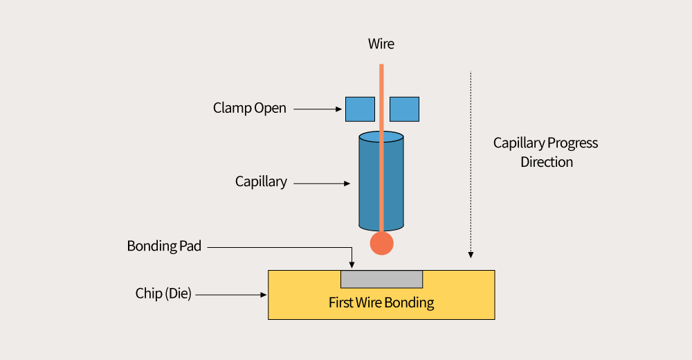
▲ Figure 5. First bond: wire ball bonding on the chip’s bonding pad
Thermosonic gold ball wire bonding, which is the most widely used among the wiring methods, includes two stages of bonding. In the first bond, the gold wire passes through the hole in the center of the capillary, and when the temperature is raised at the end of the wire, the gold melts and forms a gold ball. After that, heat, pressure, and ultrasonic vibrations are applied while opening the clamp that holds and releases the wire. When the capillary is touched to the bonding pad, the formed ball is bonded to the heated bonding pad. After the first ball bonding, the capillary is raised to the position slightly higher than the pre-measured looping height and moved to the pad for the second bond to form a loop.
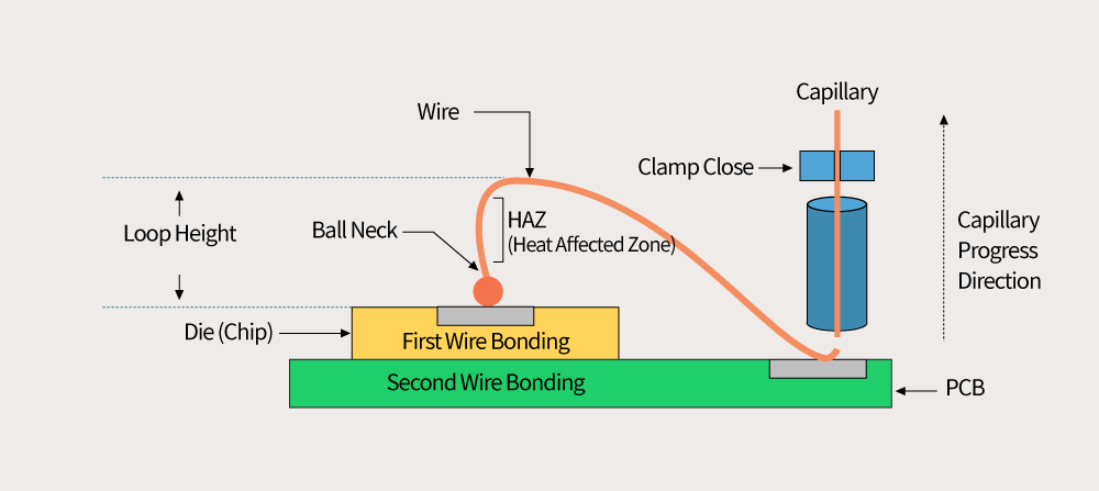
▲ Figure 6. Second bond: wire stitch bonding on the PCB’s pad
In the second bond, when heat, pressure, and ultrasonic vibration are applied to the capillary and the balls formed for the second time are crushed on the PCB pad, stitch bonding is formed. After stitch bonding, when the wire is torn in succession, it is finished with the process of tail bonding where the tail of the wire is formed weakly. After that, the capillary closes the clamp (wire holding) and tears the wire, completing the second gold wire ball bond.
Today, we looked at how the bonding method and material of wire bonding affect each other and how the wires are bonded. In this article, the reliability and the problems that can arise during wire bonding were mentioned briefly; however, what is important in wire bonding is to understand the vulnerability, solutions developed to overcome the vulnerability, and the mutual trade-off relationship. Also, it is recommended to take a look at how the bonding method has changed with the development of the package type and packaging technology.

ByJong-moon Jin
Teacher at Chungbuk Semiconductor High School