We are living in a highly advanced digital era from a technology perspective. Digital devices and technologies are so abundant that it is actually difficult to avoid running into one anywhere we go. Our cellphone is more capable in digital signal processing than a spacecraft from not too long ago; Watching a high-resolution video (or multiple videos for that matter!) is no longer an issue over digital wireless communication; Digital smart devices are providing automation capabilities for residences and offices that must have been unbelievable ten years ago. However, from an energy perspective, more than half of the entire electrical energy consumption in the world is still spent on electromechanical systems – things that move (e.g., motors, actuators, generators, etc.). Surprisingly – or unsurprisingly – the percentage of these electromechanical systems is projected to rapidly grow as electric vehicles are gaining traction in market share. Due to the mechanical nature, these systems unavoidably incur friction and vibration while working, eventually leading to lubricant dry-out, part wear-out, axle misalignment, mount stiffening and fracturing, etc. Therefore, frequent maintenance is an absolute necessity for these machines that move to guarantee adequate service and performance levels.
A Smarter Way to Do the Maintenance: CBM
When do we decide to do the maintenance? Traditionally, too late – when we learn of a failure via an obvious sign like a complete malfunction. For example, we finally realize the compressor in the air conditioner (AC) died after the AC does not blow cold air anymore. Sometimes, the obvious sign can be a utility bill that you happened to check today with twice the amount of what you usually pay on it.
It could have been the refrigerant in the AC that was slowly leaking and running low, causing the AC to work twice as hard to meet the temperature you set. These practices are conventionally called “run-to-failure” maintenance. We simply let the symptom or pathology develop further so that it essentially displays a giant, hard-to-miss sign over it that says “something is wrong.” As you can imagine, this run-to-failure approach is quite inconvenient for users. The down-time of the device or machine happened suddenly from your perspective and now you must invest time to perform a repair yourself or arrange a visit of a repair person. Money-wise, the repair also becomes a costlier fix as the root cause of the symptom must have quite progressed. For example, it could have been a simple touch-up a month ago like a retightening of bolts and nuts of a loose mount. If it went unnoticed for a while, however, so the loose mount finally came off while operating, it would have disastrous consequences like distorting the motor axle and damaging nearby electronics.
In a more regulated setting that should prevent a sudden, sporadic, and unpredictable “death” of equipment, like in military or commercial applications, “periodic” maintenance can be an alternative at the expense of resources (e.g., manpower, money, time, space, equipment, etc.). However, periodic maintenance still does not guarantee that all the potential issues are found during a maintenance event – the equipment can still break down during a mission. Furthermore, as the equipment group becomes larger in number and cost, a percentage of a designated down time for periodic maintenance to its all-time availability leads to an extremely excessive cost regardless of the actual percentage. For example, imagine a semiconductor fab with a hundred pieces of expensive equipment, each of which costing upward of tens or hundreds of millions of dollars. A 1% downtime of an individual machine allocated for periodic maintenance is equivalent to permanently losing one of such equipment at a fab level. Providing periodic maintenance, therefore, can easily become a multi-million (or even -billion) dollar upkeep, depending on the field. At this level, even a $10 million investment to get rid of the designated downtime for periodic maintenance, which sounds a lot of money, is in fact a tremendous deal. Furthermore, due to the pandemic and recent global shortage of semiconductors, halting wafer processes in semiconductor fabs for even a very short period can be extremely costly and should be avoided.
In order to resolve these issues, “condition-based maintenance (CBM)” – or sometimes referred to as “predictive maintenance” – is rapidly gaining popularity as a paradigm for maintenance. As the name suggests, CBM tries to trigger a maintenance event via monitoring the condition of equipment with the primary objective of predicting an equipment failure well before it happens. Actionable health information of the equipment, obtained by analyzing a continuous sensor data stream, will be immediately sent to the decision-maker if it is noteworthy.
Compared to run-to-failure and periodic maintenance, CBM can significantly improve the equipment reliability because an issue would be found at a very early stage even before it becomes symptomatic – like the bolt retightening example above. This advantage makes the repair cost yet another advantage because there are less things to fix with nearly no damage at that point. The repair, therefore, can be performed more easily by widely available labor, making it an even sweeter deal. The repair will also take less time with no or minimal equipment downtime if any. Naturally, CBM is of special interest to mission-critical areas, such as high-tech manufacturing, off-shore platforms, aircrafts, and spacecrafts.

▲ Figure 1. The Concept of “Condition-based Maintenance”
For CBM to work, however, there is a price to pay: we need to provide a “continuous” data on the condition of equipment, whether the equipment is in a good condition or not. In addition, for a detailed understanding of various conditions and states of the equipment, we would like “many” sensors to generate fine-grained data. A large amount of raw sensor data will be continuously generated and must be processed to draw out actionable information from it – a concise, impactful message for a decision-maker.
As you can imagine, these steps are extremely data-heavy and computation-intensive, requiring a considerable amount of powerful hardware (e.g., powerful CPU/GPU, RAM, and data storage) to perform real-time and complex computation. Furthermore, installing “many” sensors in and around the equipment is not a trivial task either. Integration or retrofit of extra sensors and computational resources into the existing equipment might not be always feasible. It will require considerable engineering of its own even if so. Another big hurdle for enabling CBM is the support for power and network. How do we power the newly retrofitted sensors and computational resources? How does a final message from one sensor reach the decision-maker?
Powering a CPS
Let us ponder on the first question. If there is a nearby power outlet for a retrofit cyber-physical system (CPS) – a recent trending name for sensor nodes, embedded systems, or Internet of Things (IoTs) – it would be an easy solution. However, not only multiple feet or meters of dangling wires from our CPS to a nearby power outlet are unsightly, but also pose various risks to the host environment: electrical and mechanical safety (after all these are vibrating or moving mechanical systems); noise and security concerns for the host systems’ electrical grid; and potential electromagnetic interference (EMI).
Because of these concerns, the “retrofit” CPS in many cases are expected to be power-independent with no grid access allowed. Then, how do we create a “non-intrusive” power supply for a CPS? A large enough battery pack might come as an attractive solution at first. However, battery alone is not a lasting solution as it eventually needs to be replaced or recharged – periodic maintenance! This essentially leaves a self-powering mechanism (i.e., wireless power transfer or energy harvesting) as the only option.
Wireless power transfer (WPT), regardless of whether it is inductive or capacitive, can send a significant amount of power through medium like air easily up to a kW level. However, it requires a dedicated transmitter on the grid/host side, bringing up the “intrusiveness” issue again at a much grander scale than dangling wires. Unless the WPT is already designed in in the host system, the high intrusiveness makes it an unattractive solution, especially when a small CPS for monitoring purposes consumes mWs or Ws at most.
![]()
▲ Figure 2. Wireless power transfer vs. Energy harvesting
Energy harvesting, on the other hand, does not intend to receive significant power from a dedicated, active transmitter on the other side. It extracts energy from an ambient energy source (e.g., light, temperature, electromagnetic fields, vibration, motion, friction, etc.), rather passively. The electrical installation/connection issues with respect to the host grid are, therefore, naturally nonexistent. However, being without a dedicated transmitter on the host side imply low power and energy densities, which mandate a large harvesting interface (i.e., area or volume) on the CPS side. Furthermore, an ambient energy source sometimes dictates the operating environment as well. For example, both photovoltaic (PV) and wind energy harvesting typically require outdoor installation and operation. Popular harvesting sources and their required interface sizes are presented in the table below. Here, a 100mW extraction is assumed, which is a reasonable target for a small CPS for monitoring.
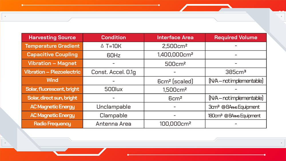
▲ Chart 1. Comparison among harvesting sources
Supplying 100mW via traditional wiring is easy. Practically any pair of wires you can find easily does 100mW (e.g., your USB charging cable can easily do 5W = 5000mW). The real benefit of the energy harvesting is that your CPS becomes independent of the external power source and wiring such that the CPS can be placed virtually anywhere. A good real-life example is an outdoor security camera around your house solely powered by a PV cell. You do not need to create a long power wiring from a closest power outlet, which might be tens of feet or meters away from where you want to install your security camera. You also do not have to worry about drilling a hole through a door or a wall and weather-sealing the holes and power lines, which are big deterrents in installing outdoor electronics. As mentioned above, however, this approach would not work indoors as the PV cell would be nearly worthless.
Let us discuss a little bit more about energy harvesting methods for powering a CPS, especially for electromechanical systems that “move” and are mostly indoors, like Overhead Hoist Transfer (OHT) equipment in semiconductor fabs shown in Figure 3. Based on the table above, piezoelectric harvesting, magnet-based vibration harvesting, or AC field-based magnetic harvesting methods are most relevant.

▲ Figure 3. OHT equipment running at the ceiling of SK hynix semiconductor fabs
Piezoelectric harvesting is based on a special material that can generate voltage across two surfaces if there is a pressure across. As a motor vibrates and causes the pressure difference between two membranes of the piezoelectric interface, the voltage is induced. The power/energy will be extracted if we connect a load or an energy storage.
Magnet-based vibration harvesting is based on a permanent magnet suspended in a rigid structure – traditionally a metal cantilever. As an electromechanical system vibrates, the metal structure and permanent magnet – especially the tip of it – will also vibrate. According to Mother Nature’s fundamental physics, the change in the magnetic field due to the vibrating magnet is closely related to and can be converted into voltage via Faraday’s law. By connecting a load, the induced voltage will start flowing a current, indicating positive power generation. This is the same principle of battery-less bike wheel lights that turn on when the wheels are spinning.
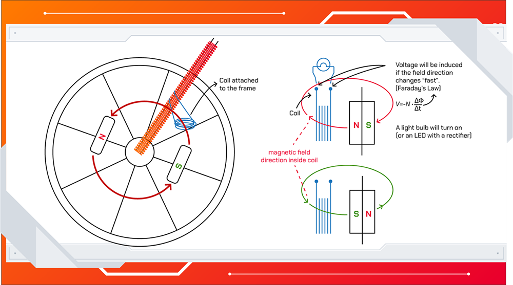
▲ Figure 4. How battery-less bike wheel lights power themselves
AC field-based magnetic harvesting is based on the host system’s AC current while operating. Again, according to physics, the AC current of the electromechanical system must generate time-changing magnetic fields around its current carrying wires. By forming an electromagnetic coupling through magnetic material and winding – similar to a typical transformer – magnetic energy can be harnessed. Connecting a load or a charge storage, like a battery or a capacitor, will result in positive energy extraction. This approach can be very efficient because the electromechanical system should be monitored when it is operating and that coincides with the energy harvesting opportunity. Another benefit of this harvesting method is that it is significantly more power dense, compared to other approaches and less prone to mechanical issues in itself.
No matter which harvesting method is selected, the take-away point is that by having a sufficient space for a harvester or bringing the power load below the harvester’s capability, a CPS can be majorly worry-free from the power and energy perspectives, promoting the global trend of environmental, social, and governance (ESG) criteria.
Issues in a CPS: Networking
The easiest way for these CPSs to communicate with a final decision-maker is to be connected to the existing network infrastructure (e.g., WiFi (or similar) of a smart factory). However, based on the host environment, such an access is not always guaranteed. For example, external networking devices would not be allowed onto the military/utility networks for obvious security reasons. Then, a surefire way to construct a messaging channel for our CPSs is to have our own, independent network without relying on the host system’s network resources – just like our self-powering harvesters. One of the viable ways is to use the CPSs themselves to build a mesh (or partial mesh) network as they will be likely scattered over a wide area. Combined with energy harvesting, this mesh topology brings an interesting challenge at a higher level: propagation of a message to the final decision-maker.
Picture a real-life case of hundreds of electromechanical systems and CPSs scattered throughout a semiconductor fab (e.g., various pumps, actuators, and generators). The motors will operate at different times for different durations. The “monitoring/sleeping” frequencies of individual energy harvesting CPSs will be naturally different. Therefore, in the overall picture, hundreds of self-powered CPSs will come on- and off-line irregularly at their own paces and energy reserves. Based on which CPSs are alive at the moment, an important message from one CPS might or might not have a complete path to reach the final decision-maker, in which case the message must be stored somewhere in the network with a shorter expected time to reach the decision-maker than where it originated.
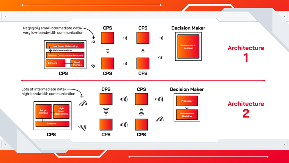
▲ Figure 5. Two approaches for a CPS architecture
“What kind of a message?” is the next question we should be asking. This concerns the architecture and data structure of a CPS. There are typically two approaches for a CPS architecture: 1) powerful onboard computation to locally produce a ‘short or no’ message (health information) and low-bandwidth communication to send it; and 2) minimal onboard computation and high-bandwidth communication to send raw sensor data. Obviously, the first option will spend minimal or no power for low-bandwidth communication (e.g., Bluetooth Low Energy (BLE)) at the expense of generally large power dissipation in the onboard computation hardware. Since the equipment health will be locally assessed, “no message” can be a response in case of a healthy motor. The second option will spend low power in computation (e.g., no processing on the raw sensor data) at the expense of large power dissipation in the high-bandwidth communication (e.g., WiFi). This option is not capable of locally deducing health information and must transmit the entire raw sensor data to the decision-maker for the “analysis.” Generally, each option has its own merits. However, in a case like this, where hundreds of CPSs can simultaneously generate raw sensor data, even a Gbps WiFi network can be easily overrun. In addition, each CPS must be able to store gigabytes or terabytes of “simultaneous and raw” sensor data temporarily, in case of no complete path to the final decision-maker at that moment – our CPS will no longer be a simple, small monitoring device. Therefore, in this case, the option 1 – the ‘short or no’ message approach with a powerful onboard computation capability – is much more sensible, feasible, and manageable.
The Challenges and Solutions
Inferring health information from vibrational and electrical sensor data conventionally requires complex mathematical operations (e.g., time-series manipulation, domain transformation, filtering, windowing, etc.). Furthermore, calculating strategies on arranging an optimal message transfer path, based on the previous history of on- and off-line timings of hundreds of CPSs, and on selecting the optimal locations of the temporary storages for messages, if there is no complete path at the moment, is also a computationally intensive task. A powerful CPU and/or GPU and large amounts of RAM and high-speed data storage are typically employed for tens of seconds to perform such real-time computation. Such a computation system can cost thousands of dollars or more with the instantaneous power consumption over hundreds of Ws or even kWs. These constraints are well beyond reasonable operating levels of an energy harvester and a small/medium CPS.
With the aid of emerging artificial intelligence (AI) and neural network (NN) technologies, recent research publications [1, 2] showed groundbreaking advancements in developing such a computation capability in a small-scale CPS. Instead of burning hundreds of Ws, only hundreds of mW are required during complex mathematical operations – a thousand times lower power consumption. This is because the AI and NN algorithms do not need to perform the original complex mathematical operations to deduce the final answer. The AI & NN algorithms reach the same answer with an extremely high probability without performing the real math in the original implementation. On top of that, instead of thousands of dollars worth of powerful computational hardware, only tens of dollars (or even less) worth of widely available hardware is required to complete the computation – a hundred times lower cost. The physical volume and space for the computational hardware is also relatively small as there is no need for big, bulky power supplies and cooling systems. This is enabled by a highly target-oriented edge computation device, implemented by a field-programmable gate array (FPGA), with tightly hardware-optimized algorithms. In simple terms, it is extremely fast and power efficient in doing a limited set of highly optimized computation – in this case, AI and NN algorithms to deduce the “health” information of an electromechanical system. However, it is not built as an all-round player like our desktop or laptop CPUs are. Dedicating toward a highly concentrated task using AI and NN and using a highly optimized set of hardware resulted in such an incredible boost in performance, power reduction, and cost reduction.
The impact and applicability of these technologies are immense. The onboard computation capability in a tiny CPS – which was the biggest hurdle in closing the gap between the large amount of continuously collected data and lower bandwidth communication constraint – is finally becoming a reality. Data filtering, signal processing, compression, and intelligent mesh network routing can be quickly done “locally” at a negligible power consumption and a cost addition. A real “smart” device that can compute like a desktop for its task and can be sustained by a tiny energy harvester without expensive Li-ion batteries will be the fundamental block for condition-based maintenance (a.k.a predictive maintenance) in the near future.
The AI and NN software technologies are currently conquering some of the most challenging engineering problems in unexpected ways. Recent advancements in semiconductor technologies have essentially enabled such research, designs, and innovations by providing explosively increasing computational power and memory capacities at lower costs. Semiconductor manufacturers, including SK hynix, will stay extremely busy to keep up with the never-ending appetites of the software technologies on critical hardware equipment, including large data storages for massive amounts of training data for deep NNs (multilayered 4D NAND flash and storage solutions – SSD/SD card/etc.), high-speed and high-capacity memories (DRAM – HBM/GDDR6+/DDR5/LPDDR5/etc.), and fast processors.
▲ Figure 6. SK hynix’s 1anm DRAM Using EUV equipment
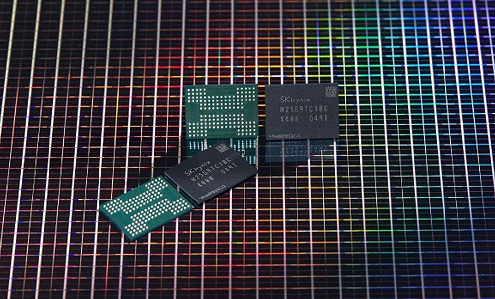
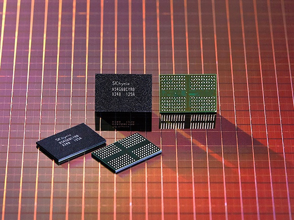
▲ Figure 7. SK hynix’s 176-layer 4D NAND flash
[Reference]
[1] S. Kang, J. Moon and S. Jun, “FPGA-Accelerated Time Series Mining on Low-Power IoT Devices,” 2020 IEEE 31st International Conference on Application-specific Systems, Architectures and Processors (ASAP), 2020, pp. 33-36, doi: 10.1109/ASAP49362.2020.00015.
*
[2] J. Chen, S. Hong, W. He, J. Moon, S. Jun, “Eciton: Very Low-Power LSTM Neural Network Accelerator for Predictive Maintenance at the Edge,” The International Conference on Field-Programmable Logic and Applications (FPL) 2021.

Jinyeong Moon Ph.D.
Assistant Professor
Electrical & Computer Engineering
FAMU-FSU College of Engineering